My Cart: 0 item(s)
Flight Systems is proud to offer this drop-in replacement for the Kohler MPAC 1000 ATS controller.
This board replaces part numbers: GM22516-A, GM85884-3, GM23262-M, GM41718, and GM73449.
Can not replace GM46975 (logic board) or GM93609, which has a different connector and off-board transfer relays.
The Flight Systems Replacement for the Kohler MPAC 1000 features:
- Complete kit with new keypad, new display, new controller, and refurbished enclosure allows for quick installation in existing MPAC 1000 mounting location.
- Exclusive feature: Set up by part number! Enter the part number of the transfer switch to automatically set defaults.
- Improved single-board design installs in place of the original two-board design. No more unreliable ribbon cable!
- 16 programmable excercise cycles that will retain their settings even if completely powered down.
- Completely configurable from front panel. No software required.
- Compatible with standard, programmed, and closed transition.
- Communicates using MODBUS protocol for remote monitoring.
- Event log not currently implemented - coming soon.
- Optional accessory boards also available:
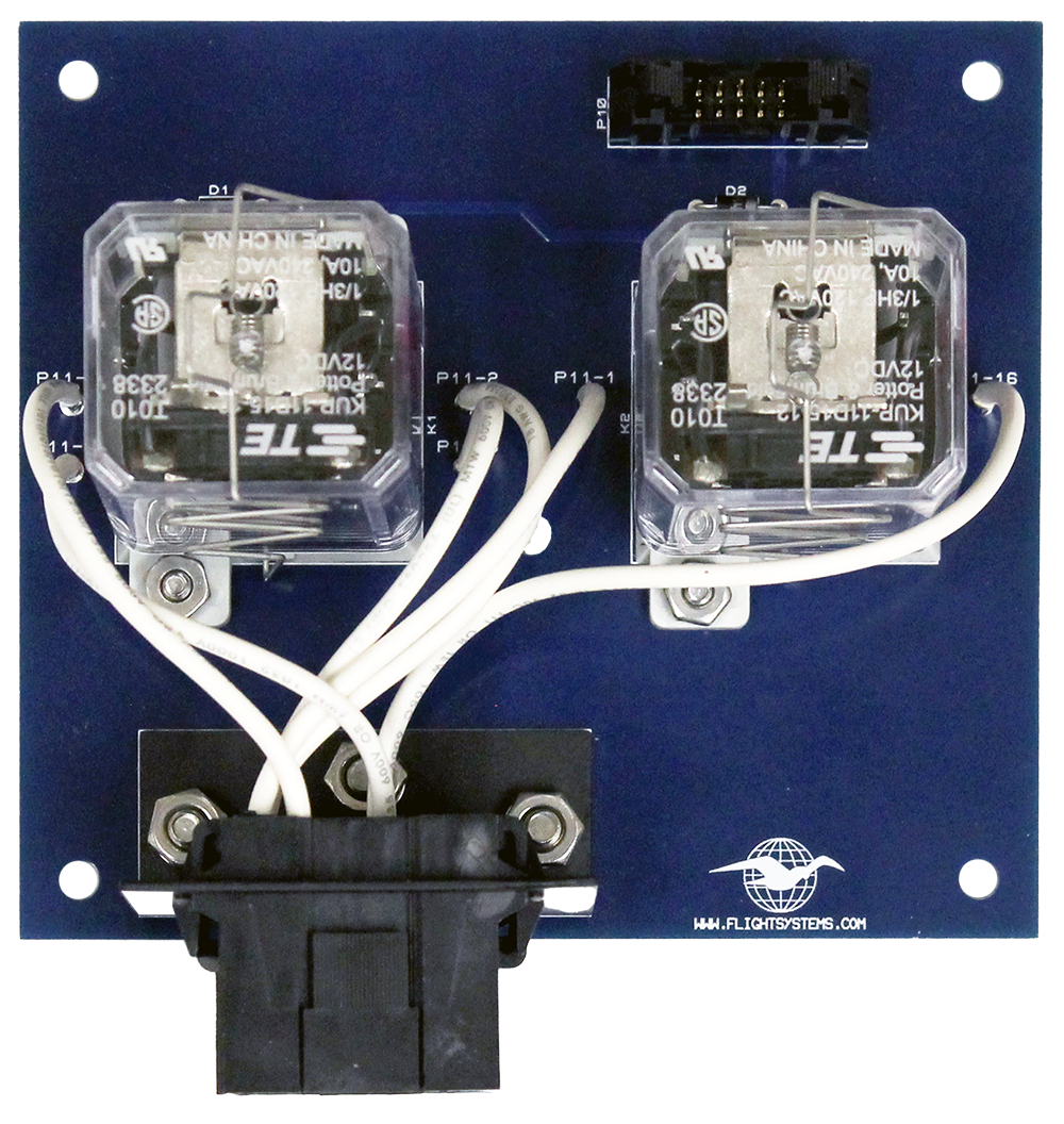
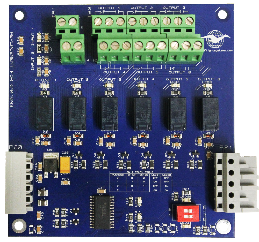
Please see the chart on the SPECIFICATIONS tab for a full list of supported features.
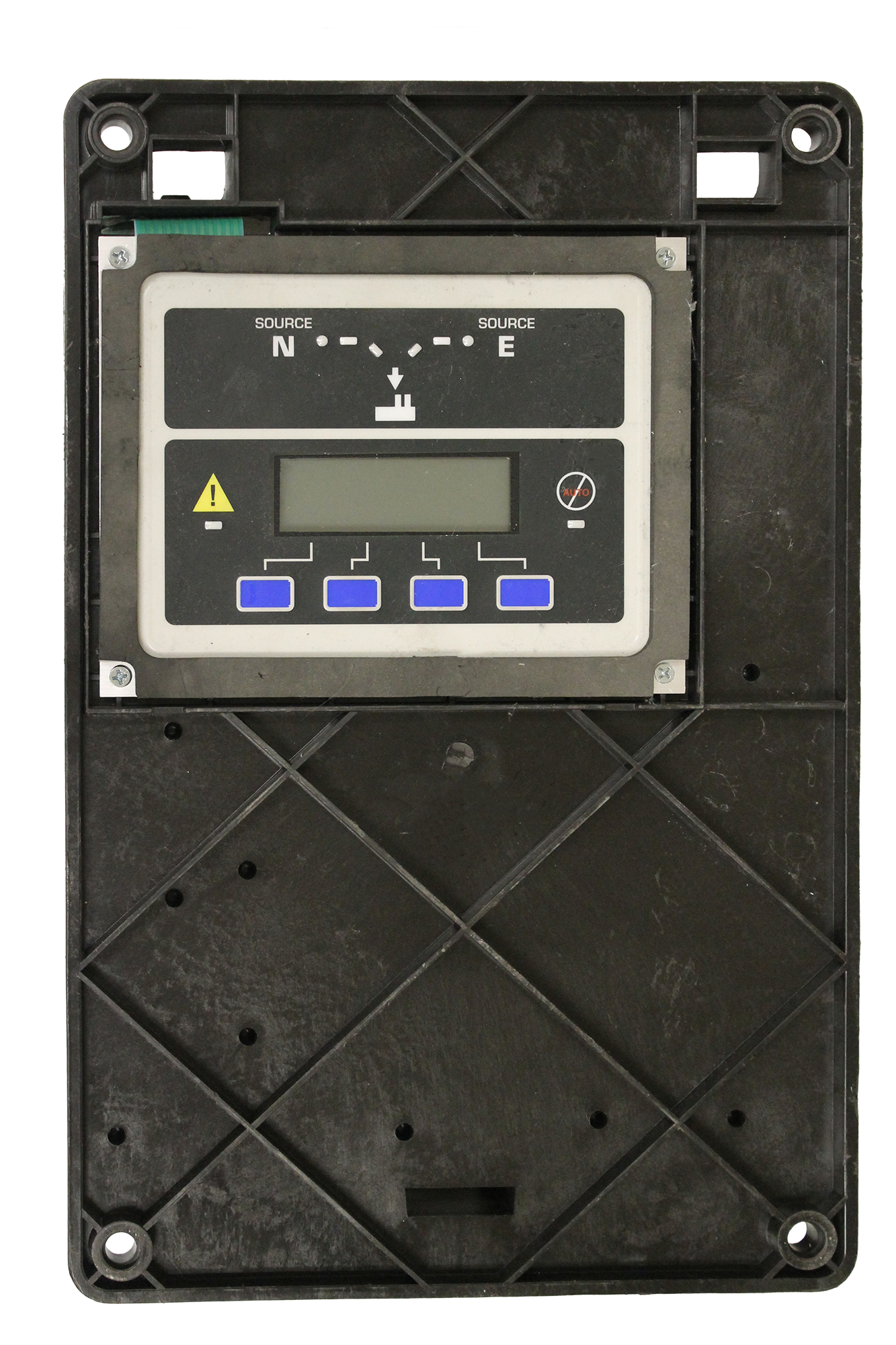
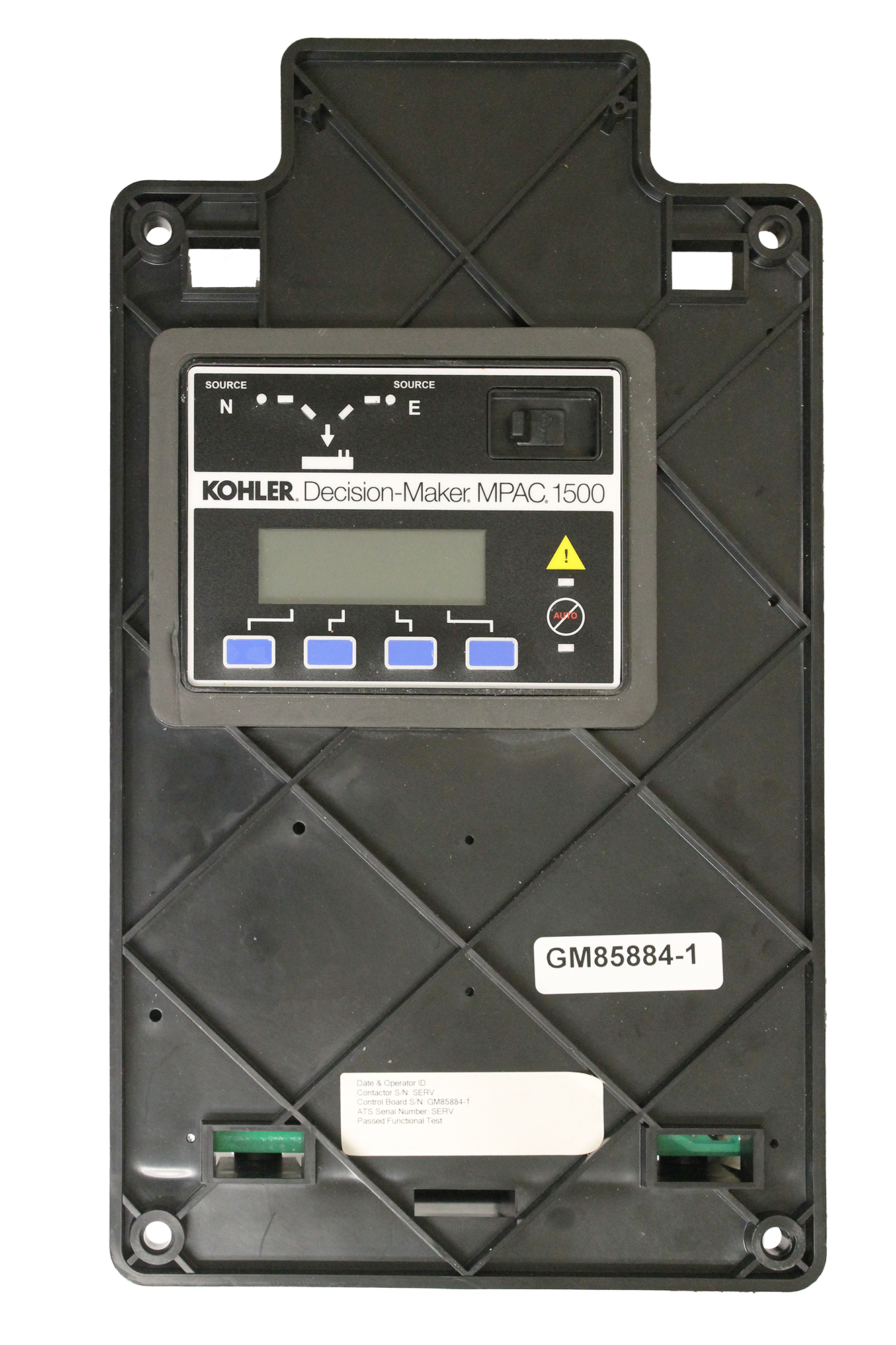
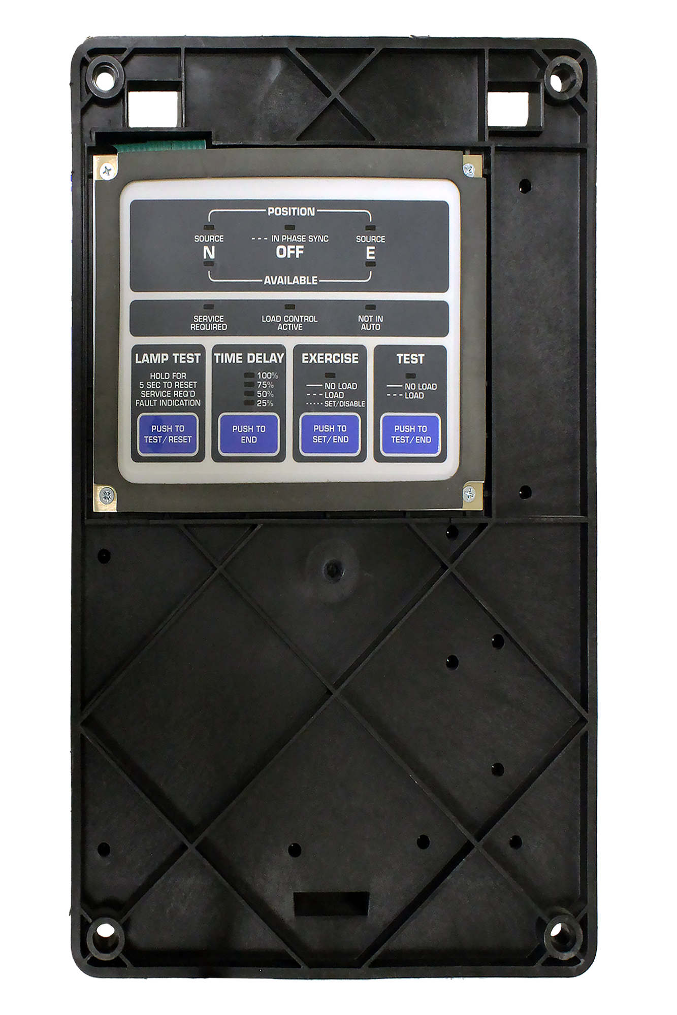
Note: There are multiple versions of the original MPAC board. Click the image below that looks like your current controller:
Feature Set:
| Fully Supported | In Development | |
| Time and Date | ||
| Time HR:MN | X | |
| Date Weekday:Month:Date:Year | X | |
| Daylight Saving Time | X | |
| 16 exercise cycles | ||
| Loaded/Unloaded | X | |
| Daily, Weekly, Monthly | X | |
| Repeat Rate | X | |
| Duration | X | |
| Start Date | X | |
| Start Time | X | |
| Source 1 Time Delays | ||
| Engine Start | X | |
| Engine Cool Down | X | |
| Transfer Preferred to Standby | X | |
| Transfer Off to Standby | X | |
| Fail to Acquire | X | |
| 9 Time-Based Load Controls | X | |
| Load Disconnect Time | X | |
| Load Reconnect Time | X | |
| Source 2 Time Delays | ||
| Engine Start | X | |
| Engine Cool Down | X | |
| Transfer Preferred to Standby | X | |
| Transfer Off to Standby | X | |
| Fail to Acquire | X | |
| 9 Time-Based Load Controls | X | |
| Load Disconnect Time | X | |
| Load Reconnect Time | X | |
| Sources | ||
| Phase Rotation | X | |
| In-phase Monitor | X | |
| In-phase Angle | X | |
| In-phase transfer Failure time | X | |
| Voltage Differential | X | |
| Frequency Differential | X | |
| Preferred Source | X | |
| Normal and Emergency | ||
| Single / 3 Phase | X | |
| Nominal Voltage | X | |
| Nominal Frequency | X | |
| Under Voltage Pickup | X | |
| Under Voltage Drop Out | X | |
| Over Voltage Pick Up | X | |
| Over Voltage Drop Out | X | |
| Voltage Debounce | X | |
| Voltage Unbalance | X | |
| Voltage Unbalance Pickup | X | |
| Voltage Unbalance Drop Out | X | |
| Under Frequency Pickup | X | |
| Under Frequency Drop-Out | X | |
| Over Frequency Pickup | X | |
| Over Frequency Drop Out | X | |
| Frequency Debounce | X | |
| Main Board / Auxiliary Board Inputs and Outputs | ||
| Inputs 1 - 2 (Main Board) & | ||
| Inputs 1-8 (Auxiliary Board) | ||
| Disabled | X | |
| Bypass Contactor Disabled | X | |
| Forced to OFF | X | |
| Inhibit Transfer | X | |
| Peak Shave Mode | X | |
| Remote End Time Delay | X | |
| Remote Common Alarm | X | |
| Remote Test | X | |
| Remote Monitor 1-4 | X | |
| Service Disconnect | X | |
| 3-Source System Disable | X | |
| Outputs 1 - 2 (Main Board) & | ||
| Outputs 1-24 (Auxiliary Board) | ||
| 3 Source System Disable | X | |
| Alarm Silenced | X | |
| Audible Alarm | X | |
| Aux Switch Fault | X | |
| Aux Switch Open | X | |
| Common Alarm 1 | X | |
| Common Alarm 2 | X | |
| Contactor in OFF | X | |
| Contactor in Preferred | X | |
| Contactor in Source E | X | |
| Contactor in Source N | X | |
| Contactor in Standby | X | |
| Exerciser Active | X | |
| Fail to Acquire Preferred | X | |
| Fail to Acquire Standby | X | |
| Fail to Transfer | X | |
| Fail to Open Source 1 | X | |
| Fail to Close Source 1 | X | |
| Fail to Open Source 2 | X | |
| Fail to Close Source 2 | X | |
| Lost Communication | X | |
| In-phase Monitor | X | |
| Load Bank Active | X | |
| Load Control Active | X | |
| Load Control 1-9 | X | |
| Non-emergency Transfer | X | |
| Not in Auto Mode | X | |
| Peak Shave Active | X | |
| Preferred Source Available | X | |
| RDO 1-4 | X | |
| Service Disconnect | X | |
| Emergency Rotation Error | X | |
| Emergency Loss of Phase | X | |
| Emergency Over Frequency | X | |
| Emergency Overvoltage | X | |
| Emergency Start | X | |
| Emergency Under Frequency | X | |
| Emergency Under Voltage | X | |
| Emergency Unbalanced | X | |
| Normal Rotation Error | X | |
| Normal Loss of Phase | X | |
| Normal Over Frequency | X | |
| Normal Overvoltage | X | |
| Normal Start | X | |
| Normal Under Frequency | X | |
| Normal Under Voltage | X | |
| Normal Unbalanced | X | |
| Normal Standby Available | X | |
| Test Mode Active | X | |
| Common Alarms | ||
| Alarm Group 1 | X | |
| Alarm Group 2 | X | |
| System Settings | ||
| Service Entrance | X | |
| Rated Current | X | |
| Peak Shave TD Bypass | X | |
| 3-Source Engine Start Mode | X | |
| Source Type | ||
| Utility - Generator | X | |
| Utility - Utility | X | |
| Utility - Generator - Generator | X | |
| Generator - Generator | X | |
| Transition Type | ||
| Standard | X | |
| Programmed | X | |
| Closed | X | |
| Transfer Commit | ||
| Commit | X | |
| No Commit | X | |
| Remote Test Loading | ||
| Loaded | X | |
| Unloaded | X | |
| Passwords | ||
| Settings password | X | |
| Test password | X | |
| Calibration | X | |
| Normal L-N | X | |
| Normal L-L | X | |
| Emergency L-N | X | |
| Emergency L-L | X | |
| Set Part Number - New feature to set defaults based on transfer switch part number | ||
| Transition | X | |
| In-phase Monitoring | X | |
| Frequency Differential | X | |
| In-phase Angle | X | |
| Nominal Voltage Settings | X | |
| Nominal Frequency Settings | X | |
| Single / 3 Phase | X | |
| Update Modules | ||
| Searches for auxiliary boards | X | |
| Save Settings | ||
| Force settings to memory (not required) | X | |
| Clear all Exercise Cycles | X | |
| Clear all Load Disconnects | X | |
| Default Calibration Settings | X | |
| Factory Defaults | Default Setting | ||
| Preferred Source | Normal | ||
| Nominal Voltage | 240 VAC | ||
| Nominal Frequency | 60Hz | ||
| Normal | Single Phase | ||
| Emergency | Single Phase | ||
| Rated Current | 200A | ||
| Operation | Utility to Generator | ||
| Passwords | 0000 | ||
| Engine Start Delay | 3 Seconds | ||
| Engine Cool Down Delay | 5 Seconds | ||
| Standby to Preferred | 60 Seconds | ||
| Preferred to Standby | 3 Seconds | ||
| Off to Preferred | 2 Seconds | ||
| Off to Standby | 2 Seconds | ||
| Fail to Acquire Preferred | 60 Seconds | ||
| Fail to Acquire Standby | 60 Seconds | ||
| Fail to Sync | 60 Seconds | ||
| Fail to Sync | Disabled | ||
| Source 1 Fail to Acquire | Disabled | ||
| Source 2 Fail to Acquire | Disabled | ||
| External Battery | Disabled | ||
| Load Controls | Disabled | ||
| Daylight Saving Time | Disabled | ||
| Inputs / Outputs | Disabled | ||
| Transfer Override | Disabled | ||
| In-Phase | Enabled | ||
| Voltage Differential | 5% | ||
| Frequency Differential | 0.1Hz | ||
| Phase Angle | 10 Degrees | ||
| Rotation Expected | ABC | ||
| Normal and Emergency | |||
| Over Voltage Dropout | 115% of Nominal | ||
| Over Voltage Pickup | 95% of Dropout | ||
| Under Voltage Pickup | 90% of Nominal | ||
| Under Voltage Dropout | 90% of Pickup | ||
| Under Frequency Pickup | 90% of Nominal | ||
| Under Frequency Dropout | 99% of Pickup |


